Air-to-Air Energy Recovery Ventilators (ERVs)
Introduction
Today’s building owners are more concerned about saving money through energy efficiency than ever before. Fortunately, air-to-air energy recovery ventilators (ERVs) help them save energy and money by recapturing 40–80 percent of the energy of the exhausted building air and using it to pre-condition incoming ventilation air. (Specific values can be found in the AHRI Directory of Certified Product Performance.) This process decreases system load and thus the amount of energy used by the system, thereby decreasing costs. This technology allows users to downsize their entire system. In most applications, costs are recouped in payback periods ranging from less than one year to three years. Read on to learn how ERVs work.
ERVs can be used effectively in any reasonably tightly constructed building with the return/exhaust air duct(s) located near the fresh make-up air intake(s). ERVs are available in three different types of the technology: rotary wheels, heat pipe exchangers, and plate exchangers.
In addition to cost savings, ERVs help buildings achieve LEED certification. This technology is certified by AHRI’s renowned certification program and governed by specific standards and guidelines.
To better understand ERVs, please see the glossary below.
The term “Energy Recovery Ventilator,” or ERV, is used here as a generic term for all air-to-air heat recovery ventilation technologies. This includes products that are typically called “Heat Recovery Ventilator” (HRV), which transfer sensible energy (temperature difference) only, and those that transfer water vapor and latent energy.
What are the advantages of ERVs?
- ERVs have the ability to transfer humidity. They can dehumidify the outside air in hot/humid climates, and keep the humidity inside the building in cold/dry climates, which improves the comfort of the building space.
- ERVs can enable the size of an air conditioner to be downsized because it reduces the latent load on the system.
- In certain operating conditions there is no need for a drain or drain pan because the ERV doesn’t produce any condensation.
- ERVs can go to lower temperatures before defrost is required, which results in energy savings.
What are the advantages of HRVs?
- In applications like pools, spas and gyms, it is preferable to not recover the humidity from the exhaust air stream. An HRV is better suited for this goal.
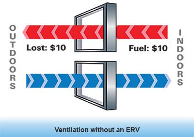
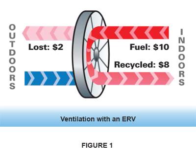
Building codes require an outdoor air supply to help control indoor air quality with the outdoor air representing a significant portion of total HVAC building load. An ERV recycles energy from the normally exhausted building air to pre-condition incoming ventilation air. By recycling energy contained in the exhaust air, ERVs lower total HVAC energy usage. This is illustrated in Figure 1 below. This process is commonly referred to as load shifting. Shifting the outdoor air ventilation load to the ERV reduces the energy demand on traditional HVAC equipment, allowing the now smaller ERV-based HVAC equipment to operate more efficiently.
Passive Energy recovery relies on the temperature and humidity difference of the two opposing air streams to perform the energy exchange. The larger the difference, the more results the ERV will provide. This trait allows energy recovery components to reduce energy consumption on days that are the hottest, coldest, and most humid. As shown in Figure 2 below, reducing energy demand allows for a more energy efficient system year round for the majority of U.S. climate zones.
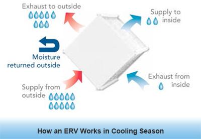
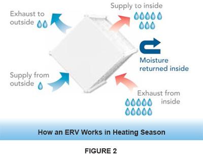
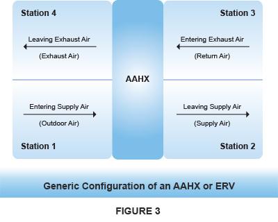
While Figure 1 illustrates a wheel and Figure 2 illustrates a plate exchanger, these Figures are intended to apply to all technologies. ERVs are sometimes referred to as air-to-air heat exchangers (AAHX) as in Figure 3 below, which illustrates a generic configuration.
The primary benefit in applying an ERV is the heating, cooling, and humidification ventilation load reductions throughout the year. Paybacks and load reductions can be calculated based on AHRI certified and verified ratings.
Effectiveness
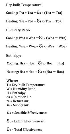
The sensible exchange is accomplished by the heat transfer matrix and the latent transfer is accomplished by the addition of a desiccant onto the transfer matrix media. Passive energy recovery relies on the difference in entering conditions of the opposing air streams to perform the exchange. An ERV’s “effectiveness” determines what the leaving condition will be. Effectiveness is further split into both sensible and latent values. A manual selection can be accomplished by using the following equations:
The ventilation load shifting accomplished by energy recovery reduces the capacity required by the chiller and boiler in a central system and that of the DX packaged unit. While it is optional to take advantage of the benefits in the central system, it is mandatory in the DX system to achieve proper control of humidity. If this is not done, the system becomes over-sized and could result in excessive moisture and occupant discomfort.
Exhaust Air Transfer Ratio (EATR)
EATR is defined as the tracer gas concentration difference between the Leaving Supply Airflow (Figure 3, Station 2) and the Entering Supply Airflow (Figure 3, Station 3) divided by the tracer gas concentration difference between the Entering Exhaust Airflow (Figure 3, Station 3) and the Entering Supply Airflow (Figure 3, Station 1) at the 100 percent rated airflows, expressed as a percentage.
If a designer is concerned about the contaminants exhausted from the building or using and ERV in a source controlled application, they need to pay particular attention to EATR. For guidance, review ASHRAE Standard 62, section 5 “Air Classification & Recirculation” on maximum EATR levels. It should be noted that if specified outside air volume is being measured at Station 2 (leaving supply airflow, Figure 3), actual outside air volume is not equal if the EATR is greater than zero.
For example:
- Require 1000 cfm (1696 m3/hr) of ventilation air for a given space
- EATR is 5 percent for the ERV under your specified pressure regime. Measured airflow at Station 2 (Figure 3) is 1000 cfm (1699 m3/hr)
- Actual outside air ventilation volume is:
- 1000 cfm (1699 m3/hr)* (1-EATR) = 950 cfm (1614 m3/hr)
- To compensate for EATR, one must increase the volume at Station 2 to 1053 cfm (1789 m3/hr)
- Airflow at Station 2 = Required Airflow for ventilation / (1-EATR)
- Airflow at Station 2 = 1000cfm (1699 m3/hr) / (1-0.05)
- Airflow at Station 2 = 1053 cfm (1789 m3/hr)
Outdoor Air Correction Factor (OACF)
OACF is defined as the entering Supply Airflow (Figure 3, Station 1) divided by the measured (gross) Leaving Supply Airflow (Figure 3, Station 2).
When specifying an ERV, it is highly recommended that the designer pay attention to the OACF, which is an indication of leakage across the heat exchanger. This leakage can occur within the heat exchanger and/or the seals between the supply and exhaust airstreams.
If the OACF is greater than one, the air is leaking from the supply air over to the exhaust air. Depending on fan configuration, it is likely one will end up requiring additional fan energy. If the OACF is less than one, the air is leaking from the exhaust air over to the supply air. The same parameters need to be taken into consideration when dealing with OACF values of less than one. Fans will not necessarily see the scheduled air volumes unless this is taken into consideration.
How should I apply OACF & EATR into my designs?
AHRI Certified manufacturers can provide details on how scheduled air volumes and overall performance are impacted by the certified EATR and OACF values. It is important to understand what the pressure differential is across the heat exchanger so that the correct OACF & EATR factors can be applied. This is why manufacturers offer multiple ratings for various pressure regimes. The AHRI Directory should be consulted for all certified ratings. When applying the technology, consult a manufacturer or representative to ensure that scheduled air volume and brake horsepower requirements are accurate.
Control and Prevent Frost
In cold climates, frost may occur in the exhaust air side of ERV-HRV. Means to avoid frost or removing frost are required to prevent damage to the heat exchanger and/or increase of pressure drop across the heat exchanger.
Some of the methods that can be used for all types of exchangers:
- Exhaust only: When frost is indicated on the component, the intake blower is de-energized for a period of time to allow exhaust air to warm component, melt frost, and drain or evaporate condensate. Alternatively, exhaust-only operation is determined based on outside air temperature to avoid frosting.
- Preheat: For outdoor air preheat, heat is provided in the outdoor air intake to heat the air to a temperature above the exchanger frost threshold before it enters the component. Alternatively, for return air preheat, heat is provided in the return air before it enters the exchanger to prevent frost from forming.
- Re-circulation: When return air or exhaust air re-circulation is used, return air or exhaust air is substituted, in whole or in part, for outside air passing through the exchanger for defrost purposes.
- Bypass: A portion of the outdoor air is bypassed around the exchanger until the frost threshold is avoided.
ROTARY WHEELS
Description:
A rotary air to air energy recovery wheel, sometimes referred to as a heat wheel, consists of a revolving cylinder filled with an exchanger matrix having a large internal surface area. A total energy recovery wheel (enthalpy wheel) will provide sensible (thermal) and latent (moisture) exchange between opposing airstreams.
![]()
Sensible energy is transferred as the matrix picks up and stores heat energy from the hot air stream and then releases it into the cold air stream as the wheel rotates.
![]()
Latent energy transfer is accomplished either through the process of adsorption or condensation/re-evaporation. In the majority of applications a desiccant is applied to the matrix to adsorb water molecules from the humid air stream and then release them into the drier stream as the wheel rotates.
![]()
Installation
The energy recovery wheel should be placed in an air distribution system where adjacent supply (ventilation) air and exhaust air streams each flow through one half of the exchanger in a counter flow pattern.
![]()
Application and Frost Prevention
Energy recovery wheels can be incorporated within the design of packaged rooftop units and accessories, air handlers, ventilators, and on site air distribution systems. Energy recovery wheels offer high enthalpy effectiveness and are easily scaled in size making them desirable in applications where space is of concern and moisture transfer between air streams is required. Wheel performance will vary by application; please consult with the AHRI Directory or the manufacturers’ documentation for specific design information.
In a wheel-based energy recovery system the possibility of cross leakage of air from one air stream to another exists. These leakages are represented by the OACF and EATR values of a certified component. Please refer to the EATR and OACF section above for more details.
Application of an energy recovery wheel in climates that experience severe winter conditions may require frost protection or defrost. Frost formation results in a reduction and eventual blockage of airflow through the heat exchanger. The temperature below which frost will begin to accumulate on heat exchanger surfaces is referred to as the frost threshold temperature. It is a function of outdoor temperature and indoor relative humidity. Figure 8 illustrates typical frost thresholds. Frost control is not required until entering air temperatures are below the threshold. Common types of frost control are air bypass, pre-heat, wheel speed control, and stop / jog functions. For specific methods and controls please consult with the unit manufacturer.
![]()
Maintenance
ERV wheels are considered to be self-cleaning with regard to particulates. Particles small enough to enter the energy transfer matrix will pass through. Larger particles attempting to enter are blown clear as the wheel rotates into the counter-flowing airstream. Because of the self-cleaning characteristics for dry particles, the presence of oil and tar based aerosols in the air being supplied or exhausted will be the major factor determining cleaning frequency. Climate and operating schedule are additional factors.
Other key points of serviceable items on ERV wheels are the motor and belt and pulley systems, and wheel bearings and seal material. Each of these parts must be checked periodically to ensure factory specifications are being met. If maintenance is required please consult the Original Equipment Manufacturer (OEM) for proper instruction.
Advantages
- High latent effectiveness (enthalpy wheels)
- Compact
- Scalable
Disadvantages
- Contains moving parts
- Volumetric crossover of air possible (EATR / OACF)
HEAT PIPE EXCHANGERS
Description
A heat pipe exchanger is a sensible only air-to-air recovery exchanger made of a multitude of interconnected or individual tubes with fins assembled together. Heat pipe exchangers are similar to cooling or heating coils but without external connection. They are completely passive devices without any moving parts.
Heat pipe’s tubes and fins are commonly made of aluminum or copper. To increase heat transfer, all tubes have an inner wick structure. Below is a summary of how heat pipes work (Figure 9).
- Each tube or group of tubes contains vaporizable liquid, usually refrigerant, and typically will have half of their length exposed to a hot air stream (evaporator side) and the other half exposed to a colder air stream (condenser side). The phase change cycle is as follows: the evaporator section absorbs heat and the liquid boils and changes phase to vapor.
- The vapor driven by inner pressure differential moves to the condenser side.
- The cold temperature of the condenser side condenses the vapor back to its liquid phase.
- The liquid, aided by gravity, flows back to the evaporator side.
![]()
Installation
Typically, a heat pipe is installed with the tubes in the horizontal position for a side by side air streams configuration. When level the heat pipe can be used during summer and winter conditions without any moving mechanism. The evaporator and condenser section will naturally switch sides when the outside air becomes hotter or colder than the return air.
When used with an angle or vertically, the evaporator (hottest air stream) needs to be the lowest section of the heat pipe. A heat pipe can be installed permanently with an angle or vertically, but that will restrain its use for one season only. If installed with a tilting base mechanism that can reverse the angle it could be used in both seasons but at the cost of adding moving parts to the system that typically would not have moving parts.
Application and Frost Prevention
Heat pipe exchangers are durable, compact, and customizable exchangers, making them well suited for applications where specific dimensions and EATR & OACF levels must be reached. Heat pipes can be used with stainless steel casings & various coatings for corrosive or harsh environments.
Different methods can be used for frost prevention or defrosting, including preheating re-circulation and bypass. Tilt mechanism is a method to avoid frosting specific to heat pipe exchangers. When the frost threshold is reached, the tilt angle is changed, reducing effectiveness until the frosting threshold is avoided or the heat transfer is stopped.
Maintenance
Without a tilting base, heat pipe maintenance is very low. Cleaning can be done with common pressure washers using water alone or water with detergents.
Advantages
- Compact
- Customizable
- Best EATR and OACF rating
- No moving parts
- Highest durability
Disadvantages
- Lowest effectiveness
- Mostly used for side by side airflows configuration
- May contain high global warming potential (GWP) refrigerants
PLATE EXCHANGERS
Description
A static device used in building ventilation systems for transferring energy from one air stream to another. Plate exchangers are also known as ERV or HRV Cores, Enthalpy Cores, Energy or Heat Recovery Cores, Air to Air Plate Exchangers, or Air to Air Heat Exchangers. Plate exchangers are available in different sizes offering a range of airflow and ventilation capacities.
![]()
Cross-flow and Counter-flow Plate Exchangers
- In cross-flow exchangers the two air streams are perpendicular to each other. Cross-flow exchangers typically have lower energy recovery effectiveness, but lower pressure drops. They also are typically lower cost.
- In counter-flow exchangers the two air streams are parallel and opposite to each other. Counter-flow exchangers typically have higher performance but are more expensive and have higher pressure drops.
![]()
Installation
The plate exchanger can be placed in an air distribution system in a variety of orientations, and the air can travel in either direction. Multiple exchangers can be arranged in arrays to handle larger airflows.
![]()
Application and Frost Prevention
Plate exchangers can be incorporated within the design of packaged rooftop units and accessories, air handlers, ventilators, and on site air distribution systems. Energy recovery exchangers are used in a wide range of applications and are commonly used where moisture recovery is desired, low EATR is desired or there are height limitations for the air handling system.
For plate exchangers different methods can be used for frost prevention or defrosting: Preheat re-circulation and bypass. Cold corner damper or traversing defrost are other specific method to defrost a plate exchanger. Those methods prevent outside air entering a portion of the plate exchanger, yet enable the exhaust air energy to defrost that section of the component.
Maintenance
- Filters are typically installed in front of the two faces of the core on the incoming air streams to collect any particulate.
- Most cores can have their surfaces vacuumed or rinsed with water to remove any particulate that has passed the filter.
- As always, make sure to follow the specific manufacturer’s maintenance instructions.
Advantages
- No moving parts
- No or low leakage/cross-over of contaminants (low EATR and low OACF) resulting in no need for a purge
- The air streams do not mix and have complete separation between the exhaust air and the fresh air stream
- Can be manufactured in different sizes, plate spacings and arranged in different orientations to enable optimal performance, pressure drop and packaging configurations
Disadvantages
- May take up a larger footprint in larger air flow systems.
Using ERV systems is a great approach to achieving LEED certification in a building. Two prerequisites can be covered when modelling and implementing an ERV:
- LEED Indoor Environmental Quality Prerequisite 1, Minimum Indoor Air Quality Performance with reference to ASHRAE Standard 62.1-2007, Ventilation for Acceptable Indoor Air Quality
- LEED Energy and Atmosphere Prerequisite 2, Minimum Energy Performance with reference to ASHRAE Standard 90.1-2007, Energy Standard for Buildings Except Low-Rise Residential Buildings
The difference between these two prerequisites is that one requires outside air for ventilation and the other requires that outside air ventilation be managed as efficiently as possible. Energy recovery devices permit HVAC system designers to accomplish both of these intents in an effective manner.
An ERV recovers energy from exhaust air to pre-treat the outside air, which reduces the load the HVAC unit must handle, thereby reducing the required capacity of the mechanical equipment. An ERV will bring in the required outside air for ASHRAE Standard 62.1 while meeting the energy reduction requirements of ASHRAE Standard 90.1. ERV’s are a cost-effective means in reducing energy consumption without reducing indoor environmental quality.
ERVs can also help achieve LEED Indoor Environmental Quality Credit 2, Increased Ventilation, by allowing system designers to increase ventilation air by over 30 percent of ASHRAE Standard 62.1 requirements. Figure 13 below provides a summary of the potential LEED points that can be achieved using ERV technology.
![]()
The ERV certification program will complete the transition to software certification by 2021. The AHRI Directory lists the certified products for all ERV participants. The certification program will be transitioning from a point-type program to certifying the operating map. Therefore, starting in 2020, the AHRI ERV Directory will reflect those manufacturers whose selection rating software have been certified. The following metrics are tested and considered AHRI Certified:
![]()
- Sensible Effectiveness
- Latent Effectiveness
- Supply Pressure Drop
- Exhaust Pressure Drop
- EATR (Exhaust Air Transfer Ratio)
- OACF (Outside Air Correction Factor)
The Directory is constantly updated and maintained, providing the most up-to-date information possible to engineers and consumers.
To determine whether a product is AHRI certified, simply go to the Directory and select the manufacturer and the associated unit number for the product. If the product is displayed, it is AHRI certified. Users also may search for a specific ERV by model number.
Rating of Air to-Air Heat Exchangers for Energy Recovery Ventilation Equipment, and ASHRAE 84, Method of Testing Air-to-Air Heat/Energy Exchangers.
AHRI Guideline W, Selecting, Sizing, and Specifying Packaged Air-to-Air Energy Recovery Ventilation Equipment, is designed to provide a base understanding of ERV. When a designer first considers using an ERV for a project, the terminology and application of this technology can be daunting. This guideline helps introduce all the terminology and some of the system features that are required to understand the application of the ERV.
There are several pages of terms that the user needs to understand to ensure correct decisions about the ERV (e.g. EATR and net effectiveness).
Guideline W also will teach:
- Different ways ERVs can be integrated into the HVAC system
- What methods are available to keep the ERV from freezing up during operation (this is called frost protection)
- What to consider in balancing the system
- How to utilize an ERV with (or as) an economizer
- Classes of air that can (and cannot) be used with an ERV
Guideline W also gives several examples of ERVs used in various applications, such as classrooms and libraries.
AHRI Guideline V, Calculating the Efficiency of Energy Recovery Ventilation and its Effect on Efficiency and Sizing of Building HVAC Systems, is a more technical tool that provides the calculations necessary to correctly size an ERV and the associated HVAC system. This guideline is intended for the industry, including engineers, installers, contractors, and users. It provides a means for calculating the impact of applied energy recovery equipment on the energy efficiency of the heating, ventilating and air-conditioning system at a single selected operating condition. The guideline is not a rating system for Energy Recovery Ventilation (ERV) Equipment, nor does it provide a means of estimating annual energy use.
Building Performance
The industry understands the need for ventilation in buildings to dilute pollutants and help provide a healthy environment. What has not been well understood nor appreciated is the contribution that ERVs have had to the overall building operation and energy performance. Until recently, energy recovery was required only when the system required greater than 70 percent outdoor air, according to ASHRAE Standard 90.1-2007. However, as of the 2010 version this is no longer the case. An analysis by the ASHRAE Standard 90.1 Committee and the National Laboratory supporting the standard found that energy recovery is cost effective and provides energy savings. Because of this, ERVs are now included in a table within the 2010 version of the ASHRAE 90.1 Standard (Figure 14), which states that each fan system meeting the requirements of the table shall have energy recovery. The zones in the left column of Figure 14 refer to climate zones.
![]()
*Reprinted from ASHRAE Standard 90.1-2010 by permission of ASHRAE (www.ashrae.org).
Furthermore, ASHRAE Standard 189.1, Standard for the Design of High-Performance Green Buildings, required energy recovery with 60 percent effectiveness and starting at 10 percent outside air. This is the high performance building standard and does not require a cost effectiveness measure.
In addition, similar requirements are included in the 2012 version of the International Energy Conservation Code (IECC).
ASHRAE Standards 90.1-2010 and 189.1 are vital to the success of ERV in buildings. Different versions of ASHRAE Standard 90.1 have been adopted by different states; information on which version is used in your state can be found at: http://www.energycodes.gov/status-state-energy-code-adoption
AHRI Standard 1060/1061 - Performance Rating of Air-to-Air Heat Exchangers for Energy Recovery Ventilation Equipment — AHRI Standard 1060 was established to rate the performance of factory-made air-to-air energy heat exchangers for use in Energy Recovery Ventilation equipment. The standard uses the ASHRAE 84 Method of Testing Air-to-Air Heat Exchangers as the test reference. The ARI standard outlines the performance parameters to be reported in any literature.
Air to Air Energy Recovery Ventilation Equipment — Energy recovery components and packaged energy recovery ventilation which employ Air-to-Air Heat Exchangers to recover energy from exhaust air for the purpose of pre-conditioning outdoor air prior to supplying the conditioned air to the space, either directly or as part of an air-conditioning (to include air heating, air cooling, air circulating, air cleaning, humidifying and dehumidifying) system.
ANSI/ASHRAE Standard 62.1 - Ventilation for Acceptable Indoor Air Quality — Standard mandating fresh air to be brought into a building.
ANSI/ASHRAE/IESNA Standard 90.1 – Energy Standard for Buildings Except Low-Rise Residential Buildings — Standard requiring supplemental load to be provided through energy recovery means when building ventilation criteria meets a specified requirement.
ANSI/ASHRAE/USGBC/IES Standard 189.1 – Standard for the Design of High-Performance Green Buildings — Standard setting minimum effectiveness levels for energy transfer when using a recovery device.
Delta-P — The pressure drop as measured across an ERV component.
Desiccant — A Hygroscopic substance employed in energy recovery wheels to transfer moisture between opposing air streams. Desiccants are commonly chosen for their adsorption capability and high affinity for water molecules.
Effectiveness — The measure of energy recovery effectiveness not adjusted to account for that portion of the psychometric change in the leaving supply air that is the result of leakage of entering exhaust air rather than the exchange of heat or moisture between the airstreams.
Efficiency — the ratio of the work done or energy developed by a machine, engine, etc., to the energy supplied to it, usually expressed as a percentage.
Energy Recovery Ventilator (ERV) — A ventilator combining a full enthalpic air-to-air heat exchanger which transfers both sensible heat and humidity (latent heat) between airstreams with some combination of fans or blowers to provide fresh air into a building and exhaust air out of a building at minimized cost.
Enthalpy Plate Exchanger — Similar to a static plate technology in construction but the material separating the airstreams promote humidity transfer by using a Hygroscopic resin that allow moisture to permeate the material and transfer to the drier airstream.
Exhaust Air — Building return air that has been passed through the media and to be exhausted from the space.
Exhaust Air Transfer Ratio (EATR) — (%) is composed of carryover leakage resulting from the rotation of the wheel from Return air to Supply air and any seal leakage in that direction, minus the impact of purge. Purge airflow removes return air from the wheel volume before it enters the supply side of the component.
Frost Threshold — The outdoor air temperature limit when frosting begin in the exchanger. The frost threshold may vary from exchangers, effectiveness and return air temperature and humidity.
Heat Pipe Heat Exchanger — A device employing tubes charged with a fluid for the purpose of transferring sensible energy from one airstream to another. Heat transfer takes place through the vaporization of the fluid exposed to the warmer airstream and condensation of the fluid in the cooler airstream.
Frost Threshold — The outdoor air temperature limit when frosting begin in the exchanger. The frost threshold may vary from exchangers, effectiveness and return air temperature and humidity.
Heat Recovery Ventilator (HRV) — A ventilator combining an air-to-air heat exchanger which transfers sensible heat between air streams with some combination of fans or blowers to provide fresh air into a building and exhaust air out of a building.
Latent Energy — Energy containing humidity.
Net Effectiveness — The measure of energy recovery effectiveness adjusted to account for that portion of the psychometric change in the leaving supply air that is the result of leakage of entering exhaust air rather than the exchange of heat or moisture between the airstreams.
Outdoor Air Correction Factor (OACF) — Outdoor Air Correction Factor is the difference in airflow measured between OA and SA, presented as a ratio. The OACF includes air lost through purge and leakage from the outdoor air stream to the exhaust stream. Accordingly, OACF is used to size the fans.
Outdoor Air — Outdoor air entering the recovery device but not yet tempered by the media.
Plate Heat Exchanger — A device for the purpose of transferring energy (sensible or total) from one airstream to another with no moving parts. This Exchanger may incorporate parallel, cross or counter flow construction or a combination of these to achieve the energy transfer.
Preheat — An additional heat source designed to prevent frost buildup on the ERV while allowing the fresh air to continue being supplied to the building.
Purge — Purge removes exhaust air that would be otherwise carried to the supply air stream by the rotating wheel matrix. Outdoor air is used to clean or purge the wheel matrix before it rotates from the exhaust air stream to the supply air stream. The driving force for the purge stream is the pressure differential between the outdoor air and return air compartments adjacent to the wheel. Purge is accomplished by utilizing the wheel matrix or by mechanical means.
Return Air — Building exhaust air entering the recovery device that has not yet passed through the media.
Rotary Heat Exchanger — A device incorporating a rotating cylinder or wheel for the purpose of transferring energy (sensible or total) from one airstream to the other. It incorporates heat transfer material, a drive mechanism, a casing or frame, and includes any seals which are provided to retard the bypassing and leakage of air from one airstream to the other.
Sensible Energy — Dry bulb energy only without humidity factored in.
Start Stop Jog Function — Economizer mode that eliminates recovery penalty for energy recovery wheels. Accomplished by stopping the recovery wheel and pausing the recovery process when free cooling conditions exist (45 – 65 degrees F). Wheel is momentarily energized to purge wheel of any humidity or particulate matter that has built up on the wheel.
Sensible Plate Exchanger — Static plates use thermal conducting aluminum or synthetic plates to transfer energy from airstreams which are separated by the plate. This promotes sensible energy transfer only as the plate is not porous and therefore does not allow for any mixing off the airstream. This technology is typically applied in drier climates in the far north or in applications where there must be 100% isolation of airstreams.
Tempered Air — Outdoor air that has been conditioned by the recovery media
Variable Effectiveness Frost Control (Wheel Speed & Bypass Frost Control) — The process of minimizing exchanger effectiveness by changing rotational speed (wheels) or by bypassing a portion of the air around the exchanger to mitigate frost formation.